- . the voltage is DC. The tester MAY NOT detect voltage if:. the user is not holding the tester. the user is insulated from the tester with a glove or other materials. the wire is partially buried or in a grounded metal conduit. the tester is at a distance from the voltage source.
- OPERATING INSTRUCTIONS Measuring Voltages Time spent operational at voltages above 220V must be less than 60 seconds, with a cool-off time of at least 5 minutes. Tester will turn on automatically when voltage is applied. ENGLISH GFCI Testing Check the GFCI Receptacle user.
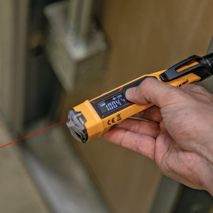
Klein Tools ET250 is a solid-state, digital voltage and continuity tester. It measures AC/DC voltages up to 600V and tests for continuity. Additionally, the ET250 tests GFCI protected circuits to verify that the GFCI device is functioning appropriately. The tester includes a backlight and worklight for working in reduced ambient lighting.
Fig. 1
Gently push down on locking tab.
Empuje suavemente hacia abajo sobre la lengüeta de fi jación.
Appuyez doucement sur la languette de verrouillage.
ENGLISH
SYMBOLS ON TESTER:
Warning. Risk of electric shock.
Risk of danger. Important information: It is important that users of this tester read, understand, and follow all
warnings, cautions, safety information, and instructions in this manual before operating or servicing this tester. Failure
to follow instructions could result in death or serious injury.
Double Insulated.
CAT IV Equipment is designed to protect against transients from the primary supply level.
(i.e. - electricity meter or overhead/ underground utility service).
OPERATING INSTRUCTIONS:
Modes of operation:
Klein Tools Voltage Tester Instructions
The NCVT-2 can operate as a dual range (NCVT-2 mode) or single range (NCVT-1 mode) tester. In NCVT-2 mode, the
tester will light a steady blue LED in the tip to indicate power-on and dual range mode. In NCVT-1 mode, the tester will
light a steady green LED in the tip to indicate power-on and single range mode.
Turn unit on:
Press and hold the power button for ½ second, then release. Listen for single-beep sound and watch for a steady green
or blue LED to illuminate in the tip of the tester. The tester is now activated and is operational. Test on known live circuit
to verify tester functionality. See Silent mode for additional power-on options.
Turn unit off:
Press and hold the power button for ½ second then release. Listen for a double-beep sound and watch the green or
blue LED turn off. The tester is now deactivated and is not operational.
System self-test:
The “power on” blue or green LED visually confi rms battery suffi ciency, system integrity, and operation/active mode.
Always test on known live circuit to verify tester functionality prior to use.
Changing operation modes:
While the unit is powered on, press and hold the power button for 2 seconds. The unit will beep 3 times and the power-on LED will
switch from blue to green or green to blue. The tester will start in whichever mode it was last powered off in.
Checking for the presence of AC voltage:
Prior to use, test on known live circuit to verify tester functionality. Place tip of the tester near an AC voltage and refer
to the tables below for each mode:
NCVT-2 mode:
POWER-ON
12 TO 48 VOLTS AC
48 TO 1000 VOLTS AC

Audible
Single Beep
Low-Pitched Pulsing Beeping Sound
High-Pitched Continuous Beeping Sound
Visual
Steady Blue LED
Blue LED Turns OFF and Red LED Blinks
(approximately 2-times per second).
Blue LED Turns OFF and Red LED
illuminates continuously.
NCVT-1 mode:
POWER-ON
12 TO 48 VOLTS AC

48 TO 1000 VOLTS AC
Audible
Single Beep

No Sound
High-Pitched Continuous Beeping Sound
Visual
Steady Green LED
Steady Green LED
Green LED Turns OFF and Red LED
illuminates continuously.
In NCVT-2 mode, the tester will be more sensitive and will show voltage indication at a further distance away from a
high voltage source than in NCVT-1 mode. Use NCVT-1 mode in situations where you expect the voltage source will
be greater than 48V AC.
Low battery indication:
Scenario 1 – Powering on the tester: The “power on” LED in the tip of the tester changes from a steady green or blue to a
blinking green or blue and a series of beeping sounds is generated. The tester then turns off. The unit is now deactivated
Klein Tools Voltage Tester Directions
and is not operational, the batteries require replacement. To replace the tester batteries refer to the Maintenance section
Klein Tools Voltage Tester Mm300 Manual
titled “Battery Replacement.”
Scenario 2 – Operating the tester: If the LED lights dim and the tone fades, the tester may require new batteries. To
replace the tester batteries refer to the Maintenance section titled “Battery Replacement.”
Auto Power Off:
After 4 minutes of non-use, the tester automatically powers off to conserve battery life. Listen for a double-beep
sound and watch the “power on” LED turn off. The tester is now deactivated and is not operational.
Silent mode:
The tester can be operated with only visual indication of voltage. With the tester powered off, press and hold the
Klein Tools Ncvt 1 Voltage Tester Manual
power button for 2 seconds then release.